Infrastructure
Pump Probe
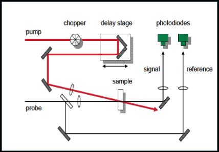
The pump probe setup employs a regeneratively amplified Ti:sapphire laser system (800 nm, 50–60 fs, 1 kHz, and 2.5 mJ; Coherent). The probe pulse is derived from single filament white light continuum generated in a 2 mm sapphire crystal. The pump pulses are derived by frequency doubling the 800 nm fundamental beam in a 100 μm β-BaB2O4 crystal (BBO), or via optical parametric amplifiers (OPA).
Streak Camera
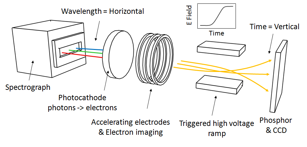
The sample is excited using 0.5µJ pulses at 400 nm of duration <100fs obtained by frequency doubling the output of a Ti:Sapph regenerative amplifier (Legend Elite Duo HE+). The excitation pulse is focused on the sample and the PL is collected and sent to a streak camera (Axis TRS, Axis Photonique Inc). Upon entering the streak camera, the light first goes through a spectrometer (Acton SP-2358i, 50g/mm, 600nm blaze). The horizontally dispersed spectral line then hits a photocathode, which emits photoelectrons whose horizontal position encode the PL wavelength. The electrons are then accelerated in a streak tube (Photonis P820). As they travel through the tube, the electrons are submitted to a dynamic high voltage, the streak ramp, which deflects them vertically according to their arrival time. The electrons then hit a phosphor screen coupled to a CCD detector (Spectral Instruments 1200 Series). The resulting image is a direct map of PL intensity as a function of time and wavelength. Only minor corrections are required for quantitative analysis. The final trace, after some binning and clipping, has an average resolution of 7 ns and 3 nm for time and wavelength, respectively.
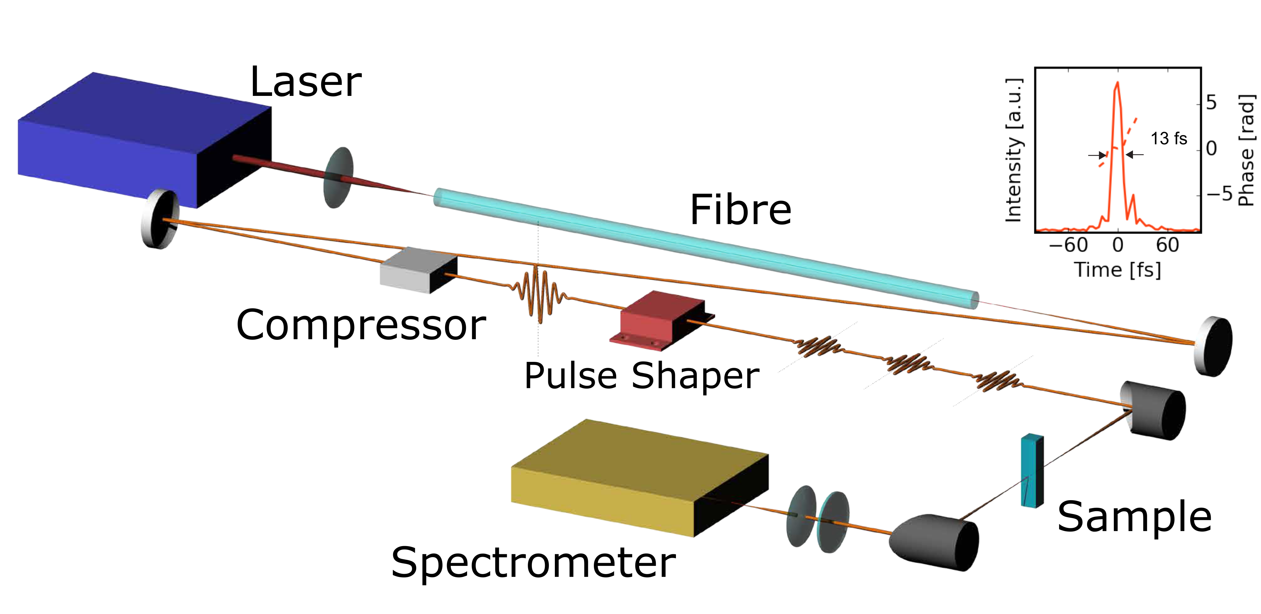
2D Spectrometer
The output of a 1 kHz, 130 fs, Ti:Sapph amplifier is attenuated with a waveplate-polarizer and focused with a 2 meter lens into a 2.5 meter long fibre of 400 microns inner diameter (few-cycle inc.). The fibre is filled with Argon and a pressure gradient is maintained by pumping the entrance of the fibre while feeding the other end with 3 atm of gas, a well-known technique to increase transmission efficiency and avoid ionization. The visible output of the fibre is selected using a shortpass filter at 700 nm. It is then collimated and downsized using a pair of spherical mirrors of foci +75 cm and -25 cm respectively. The pulses are subsequently sent to a pair of transmission GRISMs to pre-compensate for the important dispersion coming from the Acousto-Optic pulse shaper (Dazzler, Fastlite). Close to transform-limited pulses are obtained at the sample position by a combination of transmission GRISMs and pulse shaper settings. The spectral phase of the pulses at the sample position is characterized using a home-built all-reflective TG-FROG setup. The TG-FROG trace measures pulses of 13 fs. The transmitted beam through the sample contains the sum of the exciting field and all possible non-linear signals arising from the interaction with the sample. It is diffracted of a grating and sent onto a CCD array (Acton SP- 2500i and Pixis 100B, Princeton Instruments).